Node Types
Connect I/O has five different types of nodes, Inputs, Outputs, Memories, Sources and Nodes:
| Inputs | Values read from HOME I/O (e.g. light switch is on or off). |
| Outputs | Values written to HOME I/O (e.g. turn a ceiling light on or off). |
| Memories | Generic values exchanged with the simulation (read/write). For example, if the simulation is running, the current simulation date and time, etc. |
| Sources | Nodes for generating values (e.g. a Boolean, integer, float, string, etc.). |
| Nodes | Nodes providing functionalities (e.g. arithmetic operations, counters, connectivity with PLC and interface boards, etc.). |

Inputs, Outputs, Memories
The first three types, Inputs, Outputs, and Memories, are tied together with HOME I/O and their names give you an idea of their purpose. To better understand these nodes, it helps to think of Connect I/O as a controller (much like a PLC or microcontroller). Inputs are used to read values, outputs to write values and memories to read or write values to or from the simulation.
Data Types
Input, output, memory and source nodes can hold values of different data types. The following table shows all the supported data types, equivalent IEC61131-3 and range.
| Data Type | Range | IEC61131-3 | Notes |
|---|---|---|---|
| Bit | True or False | BOOL | - |
| Byte | 0 to 255 | BYTE | - |
| Short | -32,768 to 32,767 | SINT | - |
| Int | -2,147,483,648 to 2,147,483,647 | INT | - |
| Long | -9,223,372,036,854,775,808 to 9,223,372,036,854,775,807 | DINT | - |
| Float | -3.403 x 1038 to 3.403 x 1038 | REAL | - |
| Double | ±5.0 × 10−324 to ±1.7 × 10308 | LREAL | - |
| String | 64 UNICODE Characters | STRING | - |
| DateTime | 00:00:00, January 1, 0001 through 23:59:59, December 31, 9999 | DATE_AND_TIME | Represents an instant in time, typically expressed as a date and time of day. |
| Timespan | -10675199.02:48:05.4775808 to 10675199.02:48:05.4775807 | N/A | Represents a time interval that is measured as a positive or a negative number of days, hours, minutes, seconds, and fractions of a second. |
Addresses
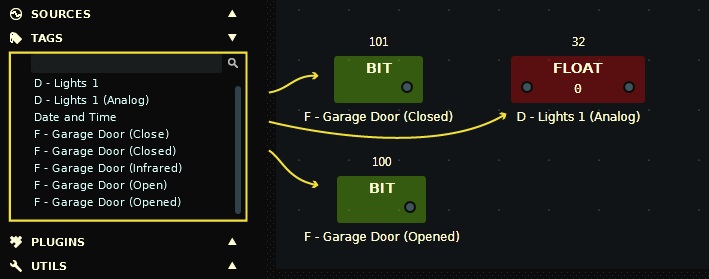
Besides a value, each input, output, and memory have an address and name. The address is used to define where the value is stored, while the name helps to identify the node's value without having to keep track of the address. It's much easier to use names than numbers to identify a node. Commonly, when an I/O (input/output) and a name is grouped together it's called a tag. On the Nodes Palette, you can find a panel called Tags where all the simulation I/O points (with a name!) are automatically detected and have the name and address already set.
Note that Inputs, Outputs and Memories have an address range per data type. Bit address range is from 0 to 512 while for other data types is from 0 to 256.
Sources
Sources nodes generate values of any data type. Typically, these nodes are used upstream in the diagram and the generated values are set by the user.
| BIT | Boolean value, click to toggle on/off. |
| Name: use it to describe this node. | |
| NUMERICAL | Numerical value (byte, short, int, long, float or double). The value type is determined by the downstream socket to which it is linked to. For example, if the downstream socket requires an integer value, it will be cast to an integer. You set the value by typing it in the input field or by dragging the slider. |
| Name: use it to describe this node. | Max: maximum possible value. | Min: minimum possible value. |
| STRING | Represents a string. Set the string value by typing it on the Value property. |
| Name: use it to describe this node. | Value: the string value. |
| DATETIME | A date and time value. |
| Name: use it to describe this node. | |
| SYSTEM TIME | The current system (computer) date and time. |
| CYCLE TIME | The diagram cycle time in milliseconds, i.e. the time it takes to update the diagram. |
