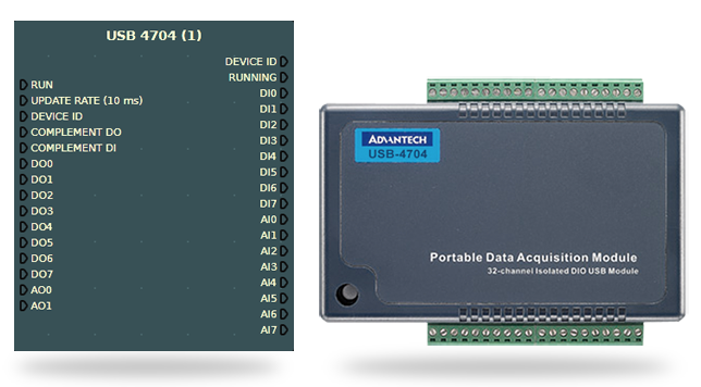
USB 4704
This node provides connectivity with Advantech USB 4704 DAQ boards. This board is commonly used as a complementary solution for the Advantech USB 4750 when analog values (0-10V) are required. It also includes digital I/O which may be used for wiring microcontrollers or any other TTL hardware (5V).
Warning
Although this board provides digital I/O, it's not opto-isolated and can't be used directly with PLC digital I/O without additional electronics.
Hardware
- Supports USB 2.0
- 8 analog inputs (12-bit resolution)
- Bipolar analog inputs (V) SE: ±10; Diff: ±1, ±1.25, ± 2, ± 2.5, ±4, ±5, ±10, ±20
- 2 analog outputs (12-bit resolution)
- Analog outputs range 0 - 5 V
- Power consumption: 5V @ 100 mA; Max.: 5 V @ 500 mA
- 8 digital I/O
- Sampling rate up to 48 kS/s
| Inputs | Description | ||
|---|---|---|---|
| Run | Start/stop board operation. | ||
| Update rate | Update rate in milliseconds (default is 16). This node runs asynchronously from the diagram update cycle. | ||
| Device ID | Board device ID, leave empty for auto. You only need to set this property when using more than one board at the same time (more on this below). | ||
| Complement ID0 | Use to complement outputs. | ||
| Complement IDI | Use to complement inputs. | ||
| DO0...7 | Digital outputs. | ||
| AO0...1 | Analog outputs [0, 5] V (USB voltage output). |
| Outputs | Description |
|---|---|
| Device ID | The current board ID. |
| Running | DAQ board operation status. |
| DI0...DI7 | Digital inputs. |
| AI0...AI7 | Analog inputs [-10, 10] V. |
How to use more than one board
When using more than one board you must set a Device ID for each node. A Device ID is a number which uniquely identifies a plugged in board. If a Device ID is not set, the first started node will connect to the board with the lowest Device ID.
After the boards are plugged into the computer (using the USB cable), they are automatically assigned with an ID (Device ID). If the boards are not unplugged, they typically keep the same ID which you should use to associate a node with a board. Note that, any time you start a node the Device ID is written into the logger.
Follow the next procedure to associate all USB 4704 nodes to their respective boards:
First, stop all the USB 4704 nodes and set all the Device ID to -1.
- Start one of the USB 4704 nodes and check on the physical board if the LED is blinking. If it's the case, this node is using this board, and you may associate them together by setting the board's Device ID on this node.
- The board Device ID is indicated in the logger ("... USB 4740 (1): Connected to USB-4704, BID#0 with device number 0). Set this value into the numerical source linked to the node's Device ID.
- Leave this node running and repeat the process for all USB 4704 nodes present in the diagram.