USB 4750
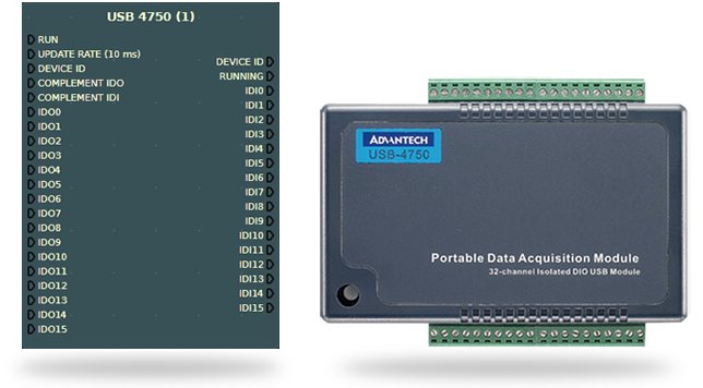
This node provides connectivity with Advantech USB 4750 DAQ boards. It's commonly used for wiring PLC or any other type of hardware requiring opto-isolated digital I/O.
Hardware
- Compatible with USB 1.1/2.0
- 16 isolated DI and 16 isolated DO channels
- High voltage isolation on all channels (2500 VDC)
- High sink current on isolated output channels (100 mA/Channels)
- Input range: 5 - 50 VDC
- Output range: 5 - 40 VDC
- Suitable for DIN-rail mounting
Node Properties
| Inputs | Description |
|---|---|
| Run | Start/stop board operation. |
| Update rate | Update rate in milliseconds (default is 16). This node runs asynchronously from the diagram update cycle. |
| Device ID | Board device ID, leave empty for auto. You only need to set this property when using more than one board at the same time (more on this below). |
| Complement ID0 | Use to complement outputs. |
| Complement IDI | Use to complement inputs. |
| IDO0...15 | Digital outputs. |
| Outputs | Description |
|---|---|
| Device ID | The current board ID. |
| Running | DAQ board operation status. |
| IDI0...15 | Digital inputs. |
How to use more than one board
When using more than one board, you must set a Device ID for each node. A Device ID is a number which uniquely identifies a plugged in board. If a Device ID is not set, the first started node will connect to the board with the lowest Device ID.
After the boards are plugged into the computer (using the USB cable), they are automatically assigned with an ID (Device ID). If the boards are not unplugged, they typically keep the same ID which you should use to associate a node with a board. Note that, any time you start a node the Device ID is written into the logger.
Follow the next procedure to associate all USB 4750 nodes to their respective boards:
First, stop all the USB 4750 nodes and set all the Device ID to -1.
- Start one of the USB 4750 nodes and check on the physical board if the LED is blinking. If it's the case, this node is using this board, and you may associate them together by setting the board's Device ID on this node.
- The board Device ID is indicated in the logger ("... USB 4750 (1): Connected to USB-4750, BID#0 with device number 0). Set this value into the numerical source linked to the node's Device ID.
- Leave this node running and repeat the process for all USB 4750 nodes present in the diagram.